Home automation using Mesh Network
- Eswar Reddy

- Apr 10, 2021
- 10 min read
Hey guys. Before getting into the project. Let me tell you why I begin this project at first place.so let’s start...
I always wanted to automate my home.so I tried some of the smart appliances out there like smart plugs, smart Led bulb, Smart fans but these things didn’t give me the results I wanted. The main problems are
First problem is
These smart things are very costly and I cannot fit a smart plug, smart Led’s and smart fan at every room in my house. And I couldn’t able to control all the appliances using a single app.
And the second problem is WIFI range. Since most of these smart things are using WIFI for communication. I had to extend my router’s range by using some other devices like WIFI repeater. So, the WIFI would be available for the smart things which are mounted at any part of my house. And this WIFI repeater will also cost me some bucks.
So, I went through some of DIY projects available on the web. But most of their finishing weren’t good as I expected and they are also using some third-party apps which has limits in add devices to it (like Blynk). and those IOT gateway also sending information individually to every control board. they are no interconnected as I expected.
So, me and my friends decided to make our home automation app and devices with certain goals in mind and they are
Easy to mount
Support the all kind of appliances (normal Led's, fan and tv),
Controlled using a single app And Interconnected.
To eliminate the WIFI range issue we decided to use the MESH technology.
We have decided to use ESP8266 microcontroller because of its support for MESH networking, internal WIFI module and Small form factor.
And for database we have decided to use the FIREBASE platform because of its support for ESP boards and its reliability,
Okay story time is over, now let jump right into process.
But before that I would suggest you to read this article for deeper knowledge:
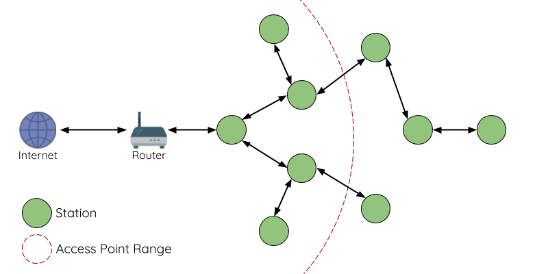
If you would have read the above article, then you might be aware about the terms parent node, child node, station, Access point, Client and all.
For mesh network we need root node which will get the information from server (Firebase) and broadcast that information to all the other nodes in the mesh.
ESP8266 cannot act as station (to other nodes in the mesh) and as client to (home’s Wi-Fi network) simultaneously. It is exceedingly difficult to configure esp8266 in the (station and client mode) mode. And sometimes this configuration may collapse the whole network also. So, the Efficient way is to use two Esp microcontrollers. One to get information from the server and another one to broadcast the information.
Schematic:

This is a schematic I prepared for PCB. If you are using the NODEMCU devkit. Then you just have to connect the D5 pin of nodemcu board 1 to D6 pin of nodemcu board 2.and the connect the D5 pin of nodemcu board 2 to D6 pin of nodemcu board 1. (Pins can be reassigned in code)
It's time for explanation.
Here the board 1 one is connected to server through home WIFI network. This board will be receiving the information from the server then that information will be transferred in the form of JSON document to the 2nd board using serial communication established between by the two wires we have connected.
Then the second board will broadcast the information in JSON format to all the other nodes in the network. Now we have created the master.
Now it time to create the slave:
Schematic for slave is bit big so I am not able to add the image of schematic with good resolution. I suggest you download it from my GitHub repository
Now we will create our smart control board. Here for switches, we have used relays and for regulators we could use PWM regulator circuit and some indicator Leds. We have connected these relay to the nodemcu GPIO pins. You can connect the signal pins of the relays to any desired GPIO pin of ESP8266.And you can make many numbers of slaves. But it is better to stop at 10 for optimum performance. for us we have made only 2 control boards for prototype purpose.
You can connect the electrical appliances in your home to these relays instead of conventional switches. Now there is no need for smart plug or smart led. For us we have used 4 switches (relays) per control boards.
Power supply:
For supply we have used the 220V-5V SMPS to stepdown the 220v to 5v.so the control board can get its own power supply from the already available electrical wires.so It wouldn't need any battery to run. (since these boards have to run 24*7.Using batteries for power supply is not an efficient choice).
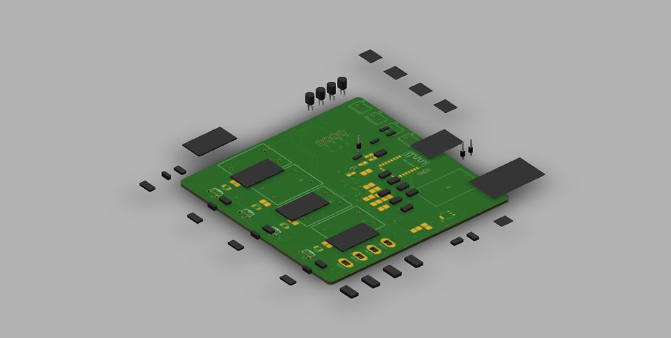
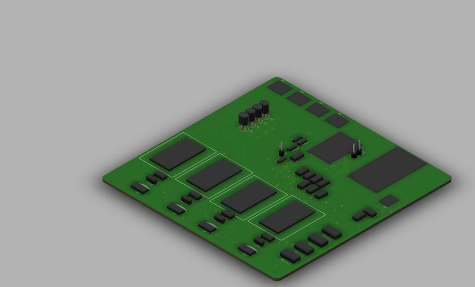
PCB:
Schematics I have shared are for PCB. If you just Wanna do some prototype then you just have connect some jumper wires according to GPIO connections made in the schematic. No need for other components like AMS power supply regulation or SMPS.
Before going through the code, I would suggest you to go through the documentation in the following repositories.so you will not face difficulties when you go through the shared codes
Task Scheduler: arkhipenko/TaskScheduler: Cooperative multitasking for Arduino, ESPx and STM32 microcontrollers(github.com)
Arduino JSON: bblanchon/ArduinoJson: 📟 JSON library for Arduino and embedded C++. Simple and efficient. (github.com)
Why JSON DOCUMENT?
We could share data without using JSON format in Master circuit. But that’s not efficient way of doing it. And there is a good chance for some data loss which may result in error. And in mesh we must send the data in JSON format. So, the data would be reaching all the nodes without any loss.
Why Task Scheduler?
When using delay, the microcontroller will pause all other operation for that time. This may collapse the whole mesh. But if we use the task scheduler it will repeat the same task for every scheduled period. It will not halt the other operations of the micro controller. You will see significance of this when you do more than transmitting and receiving the message using your ESP.
How WIFI issue got resolved?
Here the master will broadcast the message to all the nodes connected to it and then those node will again broadcast the data. so, in one way or another the end node will get message from any of the slaves or from the master. So, in this mesh networking you do not need to worry about the WIFI range. But the master must be near to the home WIFI.
And the mesh wont collapse even if any one of the nodes got disconnected. Then the mesh will reorganize its structure according to the available nodes. And adding node will not also be a problem. If the new node has the same Mesh credentials then it will automatically join in its respective MESH.
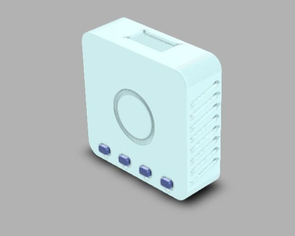
3D enclosure:
We have made an enclosure for this circuitry (4 relay). you can download that in my GITHUB repository. These are some the renderings of the 3d enclosure I have created


I have added air vents at both sides of enclosure for the ventilation of the components.
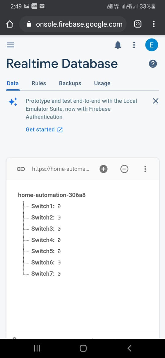
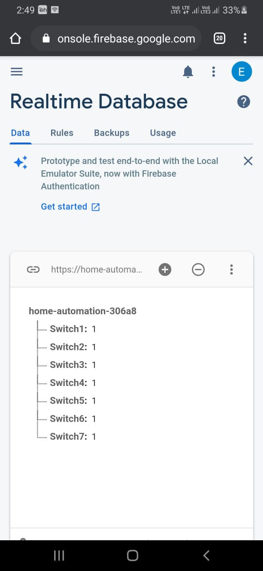
What we did on firebase?
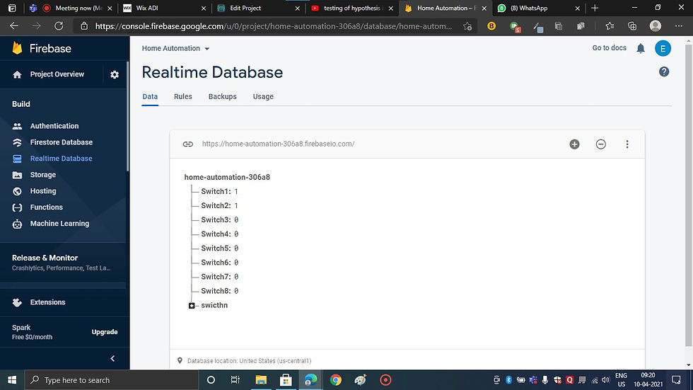
On Firebase we have created a DBMS we have created some nodes to store the values of the button that will be given from the app. and then I code we have integrated this database to the microcontroller. So, the master will fetch the data from the database and transmit the data to other nodes.
Code:
It's time to learn how we programmed the brain of the system.
Master circuitry code
#include <SoftwareSerial.h>
#include<ArduinoJson.h>
#include <FirebaseESP8266.h>
#include <TaskScheduler.h>
#include <ESP8266WiFi.h>
#define ssid "GalaxyM21" //WiFi SSID
#define password "12345678" //WiFi Password
#define FIREBASE_HOST "https://home-automation-306a8.firebaseio.com/" //Firebase Project URL Remove "https:" , "\" and "/"
#define FIREBASE_AUTH "yp5osFlS58cJGEmOkBGKBXXOgqQuadZM2ae4whYG" //Firebase Auth Token
SoftwareSerial s(D5,D6);
FirebaseData fbdo;
int node;
int Switch_Pin;
int Switch_Status;
String firebase_status;
void setup() {
s.begin(9600);
Serial.begin(9600);
WiFi.begin (ssid, password);
while (WiFi.status() != WL_CONNECTED) {
delay(500);
Serial.print(".");
}
Serial.println ("");
Serial.println ("WiFi Connected!");
Firebase.begin(FIREBASE_HOST,FIREBASE_AUTH);
}
void loop() {
if (Firebase.getInt(fbdo, "/Switch1")) {
if (fbdo.dataType() == "int")
{
node=1;
Switch_Pin=D6;
Switch_Status=fbdo.intData();
}
DynamicJsonDocument node1(1024);
node1["node"]=node;
node1["Switch_pin"]=Switch_Pin;
node1["Switch_Status"]=Switch_Status;
serializeJson(node1,s);
serializeJson(node1,firebase_status);
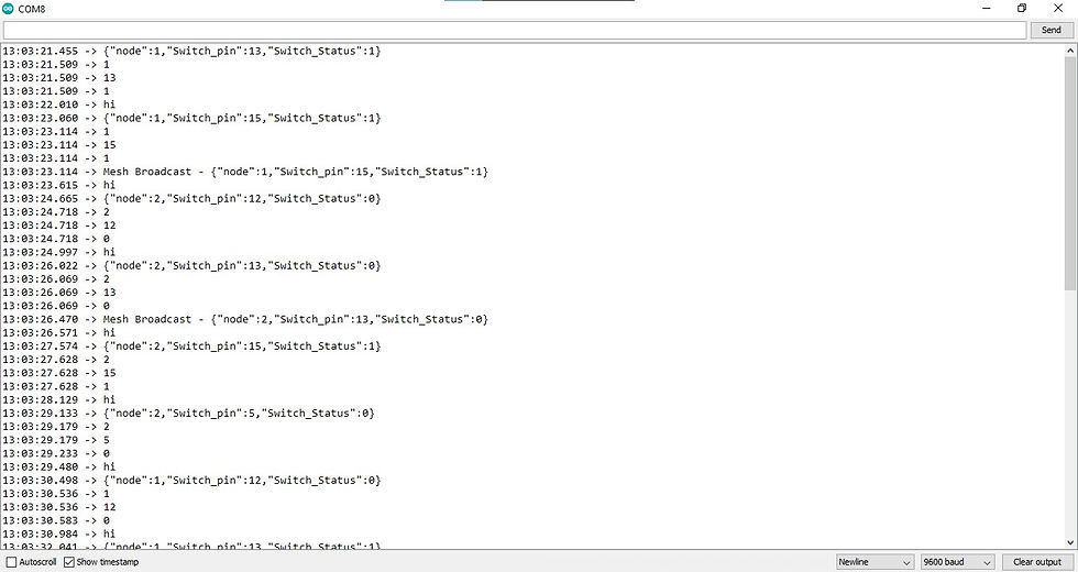
Serial.println(firebase_status);
delay(1000);
node1.clear();
firebase_status="";
}
if (Firebase.getInt(fbdo, "/Switch2")) {
if (fbdo.dataType() == "int")
{
node=1;
Switch_Pin=D7;
Switch_Status=fbdo.intData();
}
DynamicJsonDocument node1(1024);
node1["node"]=node;
node1["Switch_pin"]=Switch_Pin;
node1["Switch_Status"]=Switch_Status;
serializeJson(node1,s);
Serial.println(firebase_status);
delay(1000);
node1.clear();
firebase_status="";
}
if (Firebase.getInt(fbdo, "/Switch3")) {
if (fbdo.dataType() == "int")
{
node=1;
Switch_Pin=D8;
Switch_Status=fbdo.intData();
}
DynamicJsonDocument node1(1024);
node1["node"]=node;
node1["Switch_pin"]=Switch_Pin;
node1["Switch_Status"]=Switch_Status;
serializeJson(node1,s);
Serial.println(firebase_status);
delay(1000);
node1.clear();
firebase_status="";
}
if (Firebase.getInt(fbdo, "/Switch4")) {
if (fbdo.dataType() == "int")
{
node=2;
Switch_Pin=D6;
Switch_Status=fbdo.intData();
}
DynamicJsonDocument node1(1024);
node1["node"]=node;
node1["Switch_pin"]=Switch_Pin;
node1["Switch_Status"]=Switch_Status;
serializeJson(node1,s);
Serial.println(firebase_status);
delay(1000);
node1.clear();
firebase_status="";
}
if (Firebase.getInt(fbdo, "/Switch5")) {
if (fbdo.dataType() == "int")
{
node=2;
Switch_Pin=D7;
Switch_Status=fbdo.intData();
}
DynamicJsonDocument node1(1024);
node1["node"]=node;
node1["Switch_pin"]=Switch_Pin;
node1["Switch_Status"]=Switch_Status;
serializeJson(node1,s);
Serial.println(firebase_status);
delay(1000);
node1.clear();
firebase_status="";
if (Firebase.getInt(fbdo, "/Switch6")) {
if (fbdo.dataType() == "int")
{
node=2;
Switch_Pin=D8;
Switch_Status=fbdo.intData();
}
DynamicJsonDocument node1(1024);
node1["node"]=node;
node1["Switch_pin"]=Switch_Pin;
node1["Switch_Status"]=Switch_Status;
serializeJson(node1,s);
Serial.println(firebase_status);
delay(1000);
node1.clear();
firebase_status="";
}
if (Firebase.getInt(fbdo, "/Switch7")) {
if (fbdo.dataType() == "int")
{
node=2;
Switch_Pin=D1;
Switch_Status=fbdo.intData();
}
DynamicJsonDocument node1(1024);
node1["node"]=node;
node1["Switch_pin"]=Switch_Pin;
node1["Switch_Status"]=Switch_Status;
serializeJson(node1,s);
Serial.println(firebase_status);
delay(1000);
node1.clear();
firebase_status="";
}
Since i already shared the documentation of the libraries that i have used in this code. I feel there is no need to explain every command.so i will just explain the flow of the program.
Using software serial library we have assigned the D5 and D6 as the TX and RX pins for serial communication and since it is client ESP(the one that is connected to home and the one has to fetch the data from database) we integrated with firebase by connecting to our WIFI and by using some Firebase commands. Using getInt it will fetch the status of the switch from the database and assign it to the switch status variable. Then we have made a JSON document and serialize to the Receiver node(that is station node).
#include <SoftwareSerial.h>
#include<ArduinoJson.h>
#include <ESP8266WiFi.h>
SoftwareSerial s(D6,D5);
#define MESH_PREFIX "whateverYouLike"
#define MESH_PASSWORD "somethingSneaky"
#define MESH_PORT 5555
Scheduler userScheduler; // to control your personal task
painlessMesh mesh;
int node;
int Switch_Pin;
int Switch_Status;
String firebase_status;
// User stub
void sendMessage() ; // Prototype so PlatformIO doesn't complain
Task taskSendMessage( TASK_SECOND *1, TASK_FOREVER, &sendMessage);
void sendMessage() {
DynamicJsonDocument docmsg(1024);
docmsg["node"] = node;
docmsg["Switch_pin"] = Switch_Pin;
docmsg["Switch_Status"] = Switch_Status;
String msg ;
serializeJson(docmsg, msg);
mesh.sendBroadcast( msg );
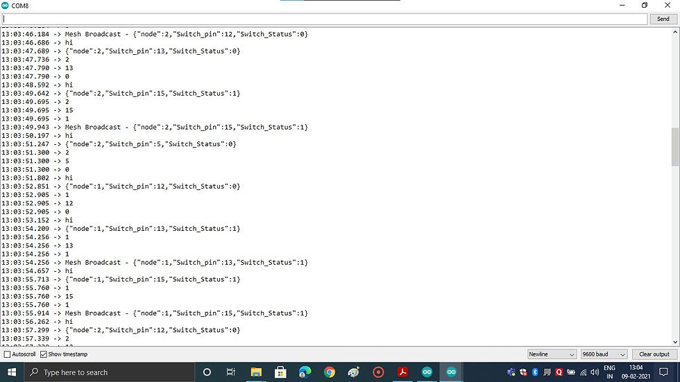
Serial.print("Mesh Broadcast - ");
Serial.println(msg);
// Needed for painless library
void receivedCallback( uint32_t from, String &msg ) {
Serial.printf("startHere: Received from %u msg=%s\n", from, msg.c_str());
}
void newConnectionCallback(uint32_t nodeId) {
Serial.printf("--> startHere: New Connection, nodeId = %u\n", nodeId);
}
void changedConnectionCallback() {
Serial.printf("Changed connections\n");
}
void nodeTimeAdjustedCallback(int32_t offset) {
Serial.printf("Adjusted time %u. Offset = %d\n", mesh.getNodeTime(),offset);
}
void setup() {
s.begin(9600);
Serial.begin(9600);
//mesh.setDebugMsgTypes( ERROR | MESH_STATUS | CONNECTION | SYNC | COMMUNICATION | GENERAL | MSG_TYPES | REMOTE ); // all types on
mesh.setDebugMsgTypes( ERROR | STARTUP ); // set before init() so that you can see startup messages
mesh.init( MESH_PREFIX, MESH_PASSWORD, &userScheduler, MESH_PORT );
mesh.onReceive(&receivedCallback);
mesh.onNewConnection(&newConnectionCallback);
mesh.onChangedConnections(&changedConnectionCallback);
mesh.onNodeTimeAdjusted(&nodeTimeAdjustedCallback);
userScheduler.addTask( taskSendMessage );
taskSendMessage.enable();
}
void loop() {
// it will run the user scheduler as well
DynamicJsonDocument docresponse(1024);
String response;
if(s.available()){
Serial.println("hi");
response=s.readString();
DeserializationError error = deserializeJson(docresponse,response);
if (error)
{
Serial.print(F("deserializeJson() failed: "));
Serial.println(error.c_str());
return;
}
Serial.println(response);
deserializeJson(docresponse,response);
node=docresponse["node"];
Switch_Pin=docresponse["Switch_pin"];
Switch_Status=docresponse["Switch_Status"];
Serial.println(node);
Serial.println(Switch_Pin);
Serial.println(Switch_Status);
}
mesh.update();
}
n the Station ESP we have deserialzed the JSON document sent by the client ESP. Then we have assigned the values obtained from the document to the respective function. In send message Function we have created the JSON document with data fetched from the database and then we have broadcasted the data to all the nodes that is connected in MESH network in form of JSON document. Here we have used Task manager to run send message function for every second.so there will be no latency. but you can program it any time period.
// Necessary Libraries
#include "painlessMesh.h"
#include <ArduinoJson.h>
// WiFi Credentials
#define MESH_PREFIX "whateverYouLike"
#define MESH_PASSWORD "somethingSneaky"
#define MESH_PORT 5555
int node;
int Switch_Pin;
int Switch_Status;
String Switch_Statusstr;
Scheduler userScheduler; // to control your personal task
painlessMesh mesh;
// User stub
void sendMessage() ; // Prototype so PlatformIO doesn't complain
Task taskSendMessage( TASK_SECOND * 1 , TASK_FOREVER, &sendMessage );
void sendMessage()
{
String msg = "Hello from node ";
msg += mesh.getNodeId();
mesh.sendBroadcast( msg );
}
// Needed for painless library
void receivedCallback( uint32_t from, String &msg )
{
//Deserializing
String json;
DynamicJsonDocument doc(1024);
json = msg.c_str();
DeserializationError error = deserializeJson(doc, json);
Serial.println(json);
if (error)
{
Serial.print("deserializeJson() failed: ");
Serial.println(error.c_str());
}
node = doc["node"];
Switch_Pin = doc["Switch_pin"];
Switch_Status = doc["Switch_Status"];
Serial.println(node);
Serial.println(int(Switch_Pin));
Serial.println(Switch_Status);
if (node == 2){
digitalWrite(Switch_Pin,Switch_Status);
Serial.println(Switch_Statusstr);
}
}
void newConnectionCallback(uint32_t nodeId) {
//Serial.printf("--> startHere: New Connection, nodeId = %u\n", nodeId);
}
void changedConnectionCallback() {
//Serial.printf("Changed connections\n");
}
void nodeTimeAdjustedCallback(int32_t offset) {
//Serial.printf("Adjusted time %u. Offset = %d\n", mesh.getNodeTime(), offset);
}
void setup() {
Serial.begin(9600);
pinMode(LED_BUILTIN, OUTPUT);
pinMode(15, OUTPUT);
pinMode(13, OUTPUT);
digitalWrite(15,LOW);
digitalWrite(13,LOW);
//mesh.setDebugMsgTypes( ERROR | MESH_STATUS | CONNECTION | SYNC | COMMUNICATION | GENERAL | MSG_TYPES | REMOTE ); // all types on
mesh.setDebugMsgTypes( ERROR | STARTUP ); // set before init() so that you can see startup messages
mesh.init( MESH_PREFIX, MESH_PASSWORD, &userScheduler, MESH_PORT );
mesh.onReceive(&receivedCallback);
mesh.onNewConnection(&newConnectionCallback);
mesh.onChangedConnections(&changedConnectionCallback);
mesh.onNodeTimeAdjusted(&nodeTimeAdjustedCallback);
userScheduler.addTask( taskSendMessage );
taskSendMessage.enable();
}
void loop() {
// it will run the user scheduler as well
mesh.update();
}
It's time to create the slave:
Here in the loop part we have deserialized the message sent from the client and added the response to respective variable. And then just to confirm dual way communication with the slave and master. we have created the send message function with some basic code. This purely for debugging you can delete it if you want. Here also we have used the Task manager to run the send message function at certain time period.
here the node is used to differentiate the control boards, you can use any datatype and any variable to differentiate the control boards.Here,
Node 1 and Switch 1 means control board 1 and relay 1
Node 1 and Switch 2 means control board 1 and relay 2
Node 2 and Switch 5 means control board 2 and relay 2
Node 2 and Switch 8 means control board 2 and relay 3 and so on
if you want use more control boards then you should increase the node and switch numbers
PICS

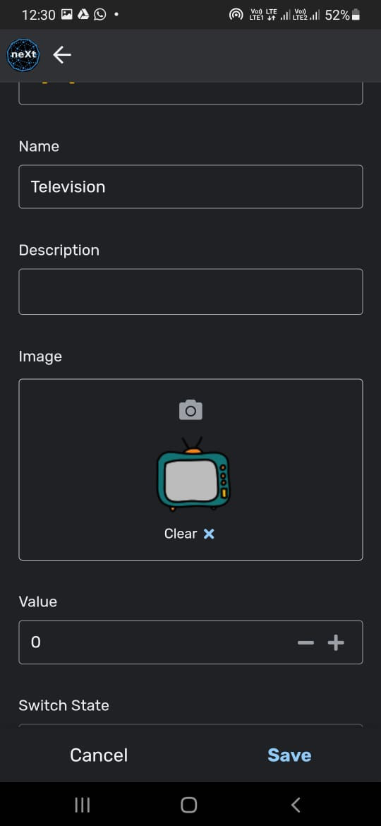
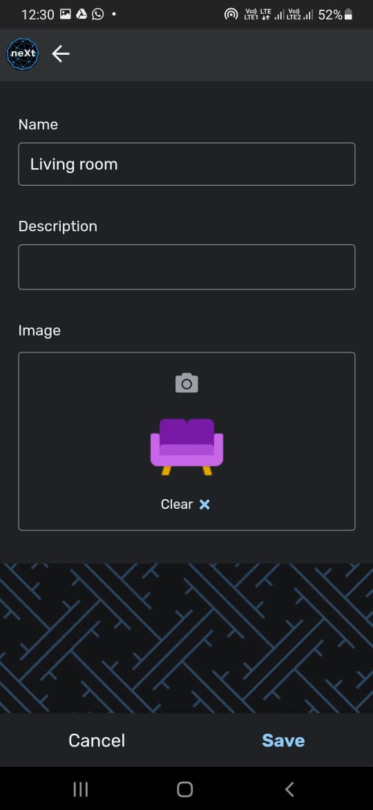
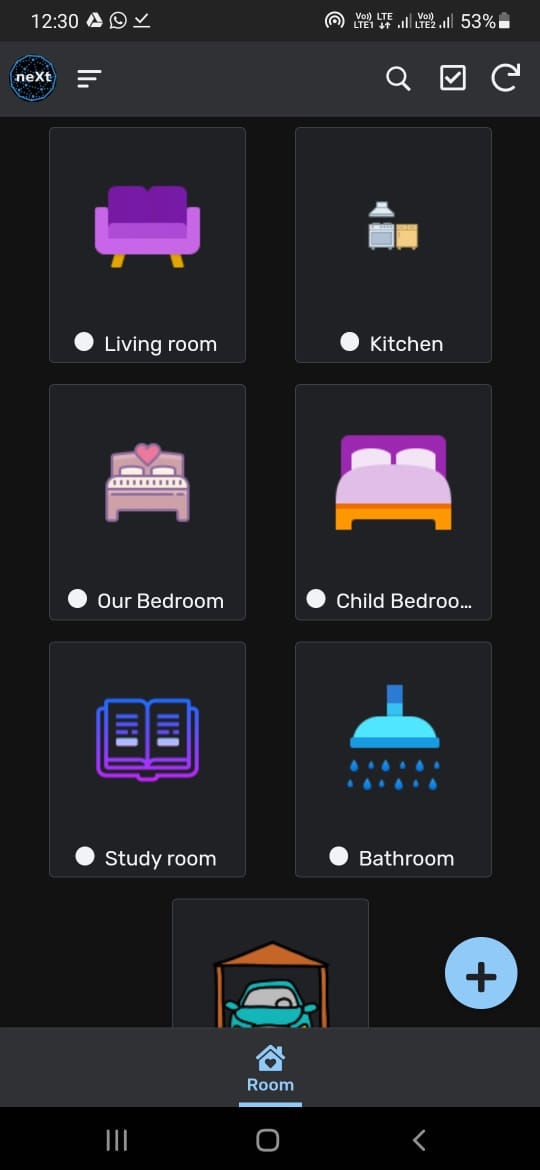
App development part:
I have created an app for this in APPSHEET.I will explain the process to build an app in appsheet in another tutorial. For now I will share some of the pics


Now let me explain the working in simple terms:
1.Once you're done with the board and 3d enclosure all you gotta do is screw the power terminals of the electrical appliances(that you want to automate) to the relays just like you do with conventional switched and mount the smart control board on wall.
2.Then place the master board in the Wi-Fi range and power it. Now within the seconds all of the nodes and master will be interlinked. Then you can control every nook and corner of your house using the App.
3.if you wanna add a new Smart control board. Then all you gotta do is enter same mesh credentials Which is used by the existing mesh network. Once you powered this new Smart Control board it will be paired with your existing network in no time. Mesh network will optimized with new structure
4.If you wanna remove a board then all you gotta do is power down. Then it will be off from the network. And again the Mesh network will alters it structure.
see how easy it is
So now onwards none of you has to worry about the WIFI range, cost or multiple IOT apps.


Comments